Shipped · 2025
Real-Time Self-Balancing Robot
An ESP32-S3 control stack that balances a two-wheel robot by coordinating high-priority sensing, PID control, motor timing, telemetry, and safety tasks.
Overview
This project is a real-time embedded control system for a two-wheel self-balancing robot built around an ESP32-S3, BNO08x IMU, and dual TMC2240 stepper motor drivers. The core challenge was not only writing a PID loop, but building the firmware from the ground up -- scheduling sensing, control, motor pulse generation, telemetry, command handling, OTA services, and safety shutdowns so the robot could react quickly without slower tasks adding jitter.
Splitting Fast Control from Slow Supervision
The robot needed to do several things at once: read the IMU, estimate pitch, run PID, generate motor step rates, accept live tuning commands, stream telemetry, watch for faults, and keep OTA/debug services available. I treated that as a scheduling problem first, then separated the firmware into a high-priority control task and a lower-priority supervisor task.
In the repo, `main/src/main.c` pins `control_core1` to Core 1 at higher priority and `supervisor_core0` to Core 0 at lower priority. The control task owns time-sensitive balance behavior, while the supervisor task polls commands, publishes telemetry, checks watchdog state, and logs slower driver diagnostics.
Closing the 100 Hz Balance Loop
The balance loop is driven by a 10 ms `esp_timer` callback. Instead of doing control work inside the timer callback, the callback sets a balance-tick flag and wakes the control task with a task notification, keeping the interrupt-style path short while still giving the control loop a deterministic 100 Hz cadence.
On each balance tick, the control task polls the BNO08x, updates the state estimator, integrates linear acceleration into a small dynamic pitch target, runs the PID controller against pitch and tilt rate, and maps the output into mirrored left/right wheel step frequencies. Keeping that entire sense-control-actuate path inside one high-priority task avoids queue latency between IMU data and motor commands.
imu_module_poll_and_log(&runtime->imu);
imu_module_read_sample(&runtime->imu, &sample);
state_estimator_update(&runtime->state_estimator, &sample, &runtime->current_pose);
total_output = pid_controller_step(&runtime->balance_pid, dynamic_target, current_pitch, current_pitch_rate, sample.timestamp_us);
runtime->test_cmd.left_step_hz = total_output;
runtime->test_cmd.right_step_hz = -total_output;
motor_module_apply_command(&runtime->motor_hal, &runtime->test_cmd);Decoupling Motor Pulse Timing
Stepper pulse generation has tighter timing needs than the 100 Hz balance loop, so the motor HAL owns a separate 10 us `esp_timer` service for step/dir pulses. The control loop updates target step frequencies, but the motor module handles the actual pulse toggling and clamps output against the live maximum step-rate cap. That separation lets PID output change at the control rate while pulse generation stays smooth enough for the TMC2240 drivers.
Keeping Tuning Responsive Without Blocking Control
The robot exposes UDP commands for `start`, `stop`, motor tests, PID gains, pitch target, velocity gain, and max step-rate cap. Commands flow through a length-1 FreeRTOS queue using overwrite semantics, so the control task reacts to the newest command instead of backing up behind stale inputs.
Telemetry is intentionally slower than the control loop. The supervisor publishes a 50 Hz CSV stream with yaw, pitch, roll, tilt rate, linear acceleration, target pitch, dynamic target, velocity gain, PID output, saturation, wheel step rates, and active-control state. That gave me enough visibility to tune the robot live without putting WiFi or logging work in the timing-critical path.
LabVIEW Control and Telemetry GUI
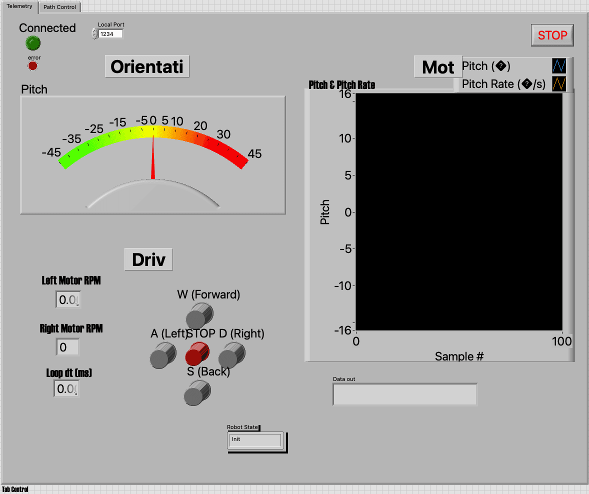
I built a LabVIEW interface for operating the robot during tests and viewing the live telemetry. The panel shows connection status, the local telemetry port, live pitch on a color-coded gauge, left/right motor RPM, loop timing, robot state, and a pitch/pitch-rate plot for watching the control response over recent samples. The directional controls and large stop button made it easier to command the robot and shut it down quickly while the graph gave insight to motor control response while tuning balance behavior on the bench.
Mechanical Design
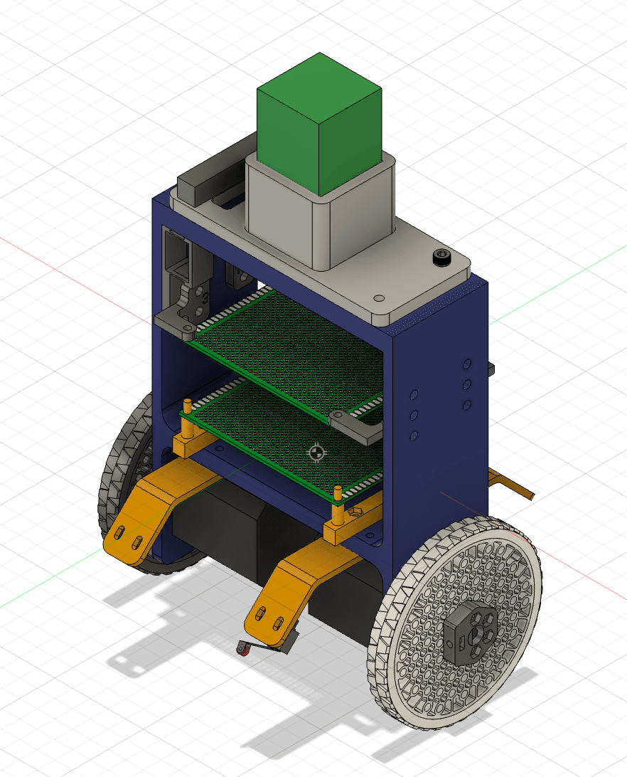
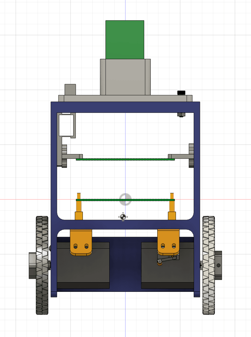
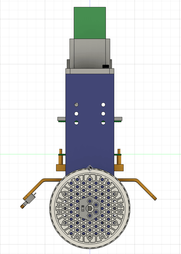
The mechanical design centered on packaging a tall, narrow two-wheel platform so the electronics, battery, IMU, motor drivers, and stepper motors could fit without making the robot impossible to balance. I used the CAD assembly to think through center-of-mass placement, wheel spacing, chassis stiffness, and service access for wiring and debugging. Because the controller reacts directly to pitch and motor response, the mechanical layout mattered as much as the firmware: loose mounting, poor mass distribution, or flex in the frame would show up immediately as oscillation, drift, or falls.
Prioritizing E-Stop and Watchdog Paths
Hardware bring-up needed immediate, boring failure behavior. A software e-stop sets a global request and wakes the control task immediately, which commands both wheels to 0 Hz, disables the motor outputs, resets PID state, clears velocity integration, and drops back to STOP mode. The IMU timeout watchdog uses the same shutdown path after 5 missed balance ticks, so bad sensor data cannot leave the robot driving on stale state.
Balancing Demo
This clip shows the robot during a balance test, where the firmware is continuously reading pitch, updating the controller, and commanding the stepper motors to keep the chassis upright. It is the clearest end-to-end view of the real-time control stack working against the physical instability of the robot.
What I Would Improve Next
I would add clearer fault-state reporting around excessive pitch angle, sustained saturation, and motor-driver diagnostics before extended free-balancing tests. Additionally, a big point of failure seemed to be IMU drift. After running the balance task for a few seconds, the robot would drift off until eventually falling over. To address this, I would like to integrate encoders on the stepper motors to gauge true position and angular velocity, then fuse that with the IMU data.